Rising Telescoping Valves
Actuation You Can See
Rising telescoping valves are used when gross indication of the valve’s position is desired during siphoning or regulating fluid levels. There are two models of rising telescoping valves to choose from depending on the needs of your application.
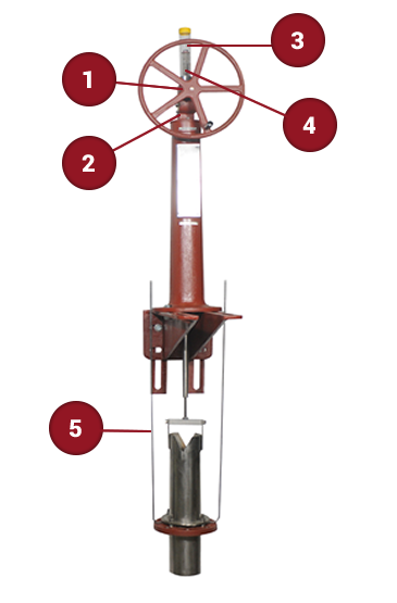
Rack and Pinion Model
Longer travel can be achieved with an easier installation process than traditional screw types. By design, this model doesn’t need anti-rotation.
A worm gear (self-locking mechanism) allows for safer, easier operation and infinite adjustment of the valve. The gear box helps the valve hold its position and not settle over time. Components are easy to replace for quick, economical maintenance. The gearbox forms a right angle from the stem, enabling the handwheel to extend closer to the operator.
The cover tube protects the rack while still enabling it to be marked at key positions for reference by operators. Weep holes minimize condensation inside the tube.
Get a highly visible, precise ¼” indication of the valve’s position with the Mylar strip.
A slip tube lubrication system pumps grease to the slip tube to help keep the companion flange working when routinely exposed to atmosphere. It is also ideal for use in a dry application.

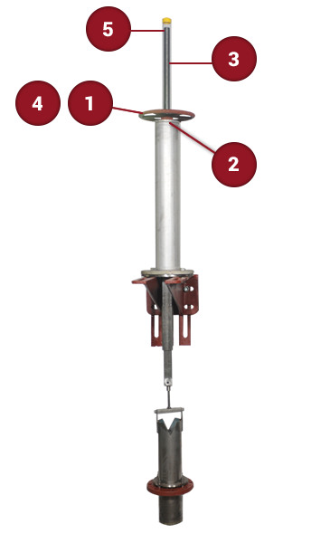
Rising Screw-Type Model
*Available in traditional or bevel gear actuation.
Traditional actuation uses a drive nut contained within a hand wheel operator.
A self-locking mechanism ensures the valve holds position and doesn’t settle over time, and allows safer operation. A bushing/thrust nut allows floor-level actuation (out of the water) and a gear reduction gives the operator a greater mechanical advantage. A right angle configuration allows safe offset applications and adjustment of the handwheel closer to the operator.
The cover tube protects the stem while still enabling it to be marked at key positions for reference by operators. Weep holes minimize condensation inside the tube.
An electric actuator can be controlled remotely from a central location, eliminating the need to send workers out to manually actuate the valve.
Get a highly visible, precise ¼” indication of the valve’s position with the Mylar strip.

Extreme Travel Tandem T-Valve Setup
For applications that require more than eight feet of travel between high and low water, two t-valves are utilized, one for high water settings and one for low water settings. A gate or plug vale shuts off the low water t-valve drain line.
You Have A Problem. We Have The Solution.
Confidence